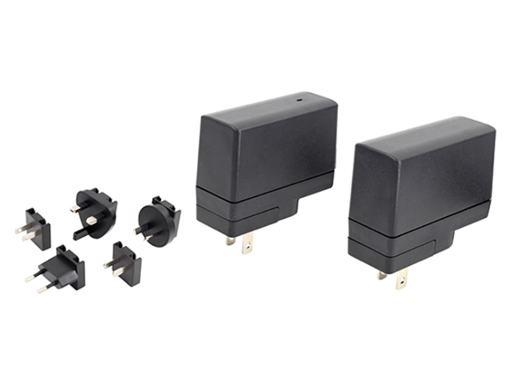
For OEMs developing battery-powered equipment, the charging system has to work as part of the complete product rather than as an isolated component. Battery voltage, capacity, charging current, connector configuration, operating temperature, and protection requirements can vary between product models. These differences can increase engineering work when a new device requires a separate charging architecture. A universal AC charger adapter can provide a standardized external power source for suitable applications, helping OEM engineers address charging compatibility while reducing unnecessary changes to the main equipment design.
Challenge 1: Matching Different Battery Voltage Requirements
One of the first challenges is matching the power source with the battery system. Different equipment may use different battery configurations, and the required charging voltage depends on the battery chemistry, cell arrangement, and charging control architecture.
An adapter should therefore not be selected simply because its output voltage appears close to the battery’s nominal voltage. The charging system must define how voltage and current are controlled during the charging process.
The UES12LCP-SPA/UES12LCP-SPC series provides output options from 4V to 24V, with power up to 12W. This range gives OEM engineers several configuration options when developing equipment that uses different low-power battery systems.
For a product family with multiple models, using a compatible external power platform can also simplify the process of evaluating different output configurations. However, each battery system still needs to be tested according to its own charging requirements.
Challenge 2: Controlling Charging Current
Battery charging is not simply a matter of supplying a fixed voltage. Current control is also important, particularly during different stages of charging.
When a battery is deeply discharged, the charging system may require a controlled current. As the battery voltage rises, the charging strategy may change. The exact charging process depends on the battery technology and the battery management circuit used in the equipment.
The adapter therefore needs to work correctly with the equipment’s charging architecture. The UES12LCP-SPA/UES12LCP-SPC series supports constant-current and conversion functions for suitable charging applications.
For OEMs, confirming the relationship between the external adapter and the internal battery management system is important. A power adapter may provide the required electrical input, while the equipment’s charging controller determines the actual battery charging behavior.
Challenge 3: Managing Abnormal Charging Conditions
Battery-powered equipment can experience abnormal conditions such as excessive current, output short circuits, or unexpected voltage changes. These conditions need to be considered during product development because a charging fault can affect both the power system and connected electronics.
Protection functions can provide an additional layer of electrical protection. The UES12LCP-SPA/UES12LCP-SPC series includes short-circuit, over-voltage, and overload protection.
These functions do not replace the battery management system. Instead, they can work alongside the equipment’s internal protection architecture. OEM engineers should define which protections are handled by the adapter and which are handled by the battery management circuit.
This separation of functions can make system requirements clearer and help engineers identify potential gaps before prototype testing.
Challenge 4: Reducing Standby Energy Consumption
Battery-powered equipment may remain connected to an external adapter even when it is not actively charging. In this situation, standby energy consumption becomes relevant.
For OEMs producing equipment in large numbers, even a small amount of standby power can become meaningful when many units remain connected for extended periods. Energy efficiency is therefore worth considering during power component selection.
The UES12LCP-SPA/UES12LCP-SPC series specifies standby power consumption of ≤0.075W and supports DOE Level VI and CoC V5 Tier 2 requirements.
These specifications can help OEMs evaluate the adapter’s energy characteristics during product planning. Actual system consumption will still depend on the equipment’s own circuits and operating state.
Challenge 5: Making the Charging System Suitable for Different Markets
OEM products are often sold across multiple regions. Different markets may use different AC plug configurations, creating an additional issue for external charging equipment.
Interchangeable AC pin configurations can allow the same adapter platform to support different regional requirements without changing the complete electrical conversion architecture.
This approach can reduce unnecessary product variations and simplify configuration during manufacturing. It is especially useful when an OEM plans to use one equipment platform across several international markets.
However, regional plug compatibility is only one part of market preparation. Applicable electrical safety, EMC, and certification requirements still need to be evaluated according to the destination market.
Challenge 6: Maintaining EMC Performance in Battery-Powered Equipment
Charging circuits and switching power converters can generate electromagnetic noise. Medical equipment and communication products may contain sensitive electronic circuits, so unwanted interference can become a system-level concern.
EMC performance depends on more than the adapter itself. Cable length, connector arrangement, grounding, filtering, PCB layout, and the position of the charging circuit can all affect the final result.
OEMs should therefore test the adapter with the actual equipment rather than relying exclusively on standalone component testing. Early evaluation can reveal whether charging operation introduces interference into displays, communication modules, sensors, or other sensitive circuits.
This is particularly important when battery charging and normal equipment operation occur simultaneously.
Challenge 7: Balancing Portability and External Power Design
Portable equipment often benefits from moving the AC conversion stage outside the main enclosure. This can reduce internal heat sources and leave more space for batteries and electronic modules.
An external adapter also allows the main product enclosure to remain focused on its functional components. However, cable length, connector durability, adapter dimensions, and weight should be considered because these factors affect practical portability.
For medical and professional equipment, the power connection may be handled frequently. Mechanical compatibility should therefore be evaluated alongside electrical specifications.
Challenge 8: Supporting OEM Development From Prototype to Production
An OEM may begin with a prototype and later produce several product versions. The charging system should ideally remain consistent enough to support this transition.
During development, engineers need to verify output performance, charging behavior, protection functions, thermal conditions, EMC performance, and mechanical compatibility. Approved samples should then provide a reference for later production.
A standardized external power solution can help reduce unnecessary changes when product quantities increase, provided the electrical requirements remain within the product’s specified range.
UE Electronic develops external power solutions for medical, communication, and industrial applications, including products designed for AC-DC conversion and charging-related applications.
Conclusion
Battery management challenges for OEMs involve more than choosing a battery with the correct capacity. Engineers also need to coordinate charging voltage, current control, protection functions, standby consumption, EMC performance, connectors, and regional power requirements.
A universal AC charger adapter can provide a practical external power platform for suitable battery-powered equipment. By separating external AC conversion from the internal battery management architecture, OEMs can gain greater flexibility when developing different equipment configurations.
The most effective selection process should begin with the complete charging system. OEMs should confirm how the adapter interacts with the battery, charging controller, protection circuits, and final equipment before approving a design. This approach can reduce integration problems and provide a clearer path from prototype development to commercial production.
